Page 1 of 1
Opentherm Gateway RS232 pin setting
Posted: Mon Dec 10, 2012 7:38 pm
by raymonvdm
Today i recieved the pic and would like to continue with the project. But i need to know which pins to connect to which pins on the SUB-D connector
On the schematic i found the following pins
Pin 3 = T1 out = RX on SUB-D = Pin 2
Pin 5 = R1 in = TX on SUB-D = Pin 3
Pin 9 = GND = GND on SUB-D = Pin 5
Is this correct ?
Re: Opentherm Gateway
Posted: Mon Dec 10, 2012 11:03 pm
by hvxl
I chose the pin layout in such a way that the cable is easy to make. That means one row of pins goes to the top row of the DB9 connector and the other row of pins goes to the bottom row of the DB9 connector.
Graphically represented (ribbon cable on the left, DB9 on the right):
1 --------------- 1
2 --------------------- 6
3 --------------- 2
4 --------------------- 7
5 --------------- 3
6 --------------------- 8
7 --------------- 4
8 --------------------- 9
9 --------------- 5
10 -----
Of course many of these pins are not connected to anything, so they don't really need to be wired.
Re: Opentherm Gateway
Posted: Mon Dec 10, 2012 11:34 pm
by raymonvdm
For now i just used an PinHeader to comport unit which was common in the time of the 486 PC

I also use 15 feet of utp (thanks Ziggo

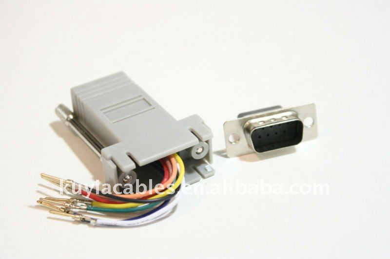
) and two of these connector
And at last

I`m seem to be able to communicated with the gateway and using the HomeSeer plugin and the OTmonitor i can see data. However i cannot see the room temperature so it seems like my boiler or thermostat is doing something strange