
I have some questions:
- How should the indicators (LEDs) are connected to the LED pin? What resistor do I need and where VCC (ground) I can connect him best.
- How the RESET must be connected?
- What the GPIO can be used?
Of course, all just looked on the site and forum but did not come out. Hence this question.
How connect LED's and RESET
Moderator: hvxl

Re: How connect LED's and RESET
How to connect the LEDs is described in this topic.
For a reset button you just need to connect a momentary switch (i.e. a switch that is only ON as long as you press it) between the two pins marked "RST".
For a reset button you just need to connect a momentary switch (i.e. a switch that is only ON as long as you press it) between the two pins marked "RST".
Schelte

Re: How connect LED's and RESET
And what about the gpio. I cannot find any usefull information about that on the website.
Disneyland, een mensenval bediend door een muis!
Re: How connect LED's and RESET
Gpio pin is only for outside temperate sensor? Wich type can i connect?
For leds, I've already read it. Now all I have how do I connecten him? Connect one side of the LED? And the other with a resistor to ground? What resistor should I use? How do I connect the LED? Is there a diagram of how this will work in them? Reset pin can I do with a jumper? Jumper connect a reset?
For leds, I've already read it. Now all I have how do I connecten him? Connect one side of the LED? And the other with a resistor to ground? What resistor should I use? How do I connect the LED? Is there a diagram of how this will work in them? Reset pin can I do with a jumper? Jumper connect a reset?
Re: How connect LED's and RESET
I'm sorry that you don't find the provided information useful.vasco_nl wrote:And what about the gpio. I cannot find any usefull information about that on the website.
Schelte
Re: How connect LED's and RESET
The GPIO pins are not only for outside temperature sensor. As mentioned on the website, with firmware 4.0b3 there are several functions to choose from:Chriskras wrote:Gpio pin is only for outside temperate sensor? Wich type can i connect?
For leds, I've already read it. Now all I have how do I connecten him? Connect one side of the LED? And the other with a resistor to ground? What resistor should I use? How do I connect the LED? Is there a diagram of how this will work in them? Reset pin can I do with a jumper? Jumper connect a reset?
- Ground - A permanently low output (0V). Could be used for a power LED.
- Vcc - A permanently high output (5V). Can be used as a short-proof power supply for some external circuitry used by the other GPIO port.
- LED E - An additional LED if you want to present more than 4 LED functions.
- LED F - An additional LED if you want to present more than 5 LED functions.
- Setback, low active - Set thermostat to setback temperature when pulled low.
- Setback, high active - Set thermostat to setback temperature when pulled high.
- DS1820 (GPIO port B only) - Data line for a DS18S20 or DS18B20 temperature sensor used to measure the outside temperature. A 4k7 resistor should be connected between GPIO port B and Vcc.
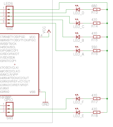
You connect the cathode of the LED to one of the LED pins of the gateway and the anode via a resistor to Vcc (not to ground). Vcc is available at the pin marked 1 on the header. You may also put the LED and the resistor in reverse order.
As mentioned on the site, use a resistor between 180 Ohm and 1 kOhm. Pick whatever value gives you the desired brightness for the type of LED you use. In the topic I referred you to earlier I have indicated the values I use.
I suggest you connect the LEDs with half of Conrad orderno 743135-89.
If you briefly put a jumper on the reset pins, that will indeed reset the gateway.
Schelte
Re: How connect LED's and RESET
I just made a schematic. Is it true if I connect them?

Bigger pic:
http://oi60.tinypic.com/jagufo.jpg
Bigger pic:
http://oi60.tinypic.com/jagufo.jpg
Re: How connect LED's and RESET
No, that's not correct. You need to connect the LEDs the other way around. And the resistors for all LEDs must be connected to Vcc, including those for LEDs 5 and 6. With 180 Ohm resistors the LEDs will be very bright.
Schelte
Re: How connect LED's and RESET
What do you mean? Can you make a schematic for my?
It's just easier to understand for me
It's just easier to understand for me
Re: How connect LED's and RESET
So nobody is able to make a picture based on the provided description and it's down to me again?
It really isn't that complicated:
It really isn't that complicated:
Schelte
Re: How connect LED's and RESET
Not for a genius like you!hvxl wrote:So nobody is able to make a picture based on the provided description and it's down to me again?
It really isn't that complicated