Re: Outside temperature probe
Posted: Thu Oct 10, 2013 10:01 pm
While this was already fixed for RedNax via a private patch, the fix is now available for everyone in firmware 4.0a10.
Domotica - Home Automation Forum
https://www.domoticaforum.eu/
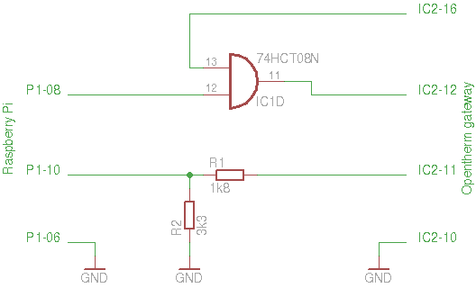
Wouldnt this imagehvxl wrote:The theory about the voltage divider part turned out to be correct, so receiving data from the gateway worked straight away in my test setup. The trouble I described was with sending commands to the gateway. That's where you would use the buffer chip. So then the circuitry would look something like this (untested):
When using buffer chips I really advise to use the 74HCT versions I mentioned. These accept TTL level signals. The 74HC versions accept CMOS level signals. Even though such a device would typically consider a voltage level above 2.7V high, the specs only guarantee a high level for anything above 3.5V. With only 3.3V available that may lead to problems, which could even be temperature dependent.
Opto-couplers have a tendency to be a bit slow to react to changes on their inputs. At 9600 baud that is probably not an issue, but I see no benefit in going that route. The gateway is already isolated on the boiler side. Isolating it at the interface side as well leaves the gateway floating. That may create more problems than it solves.
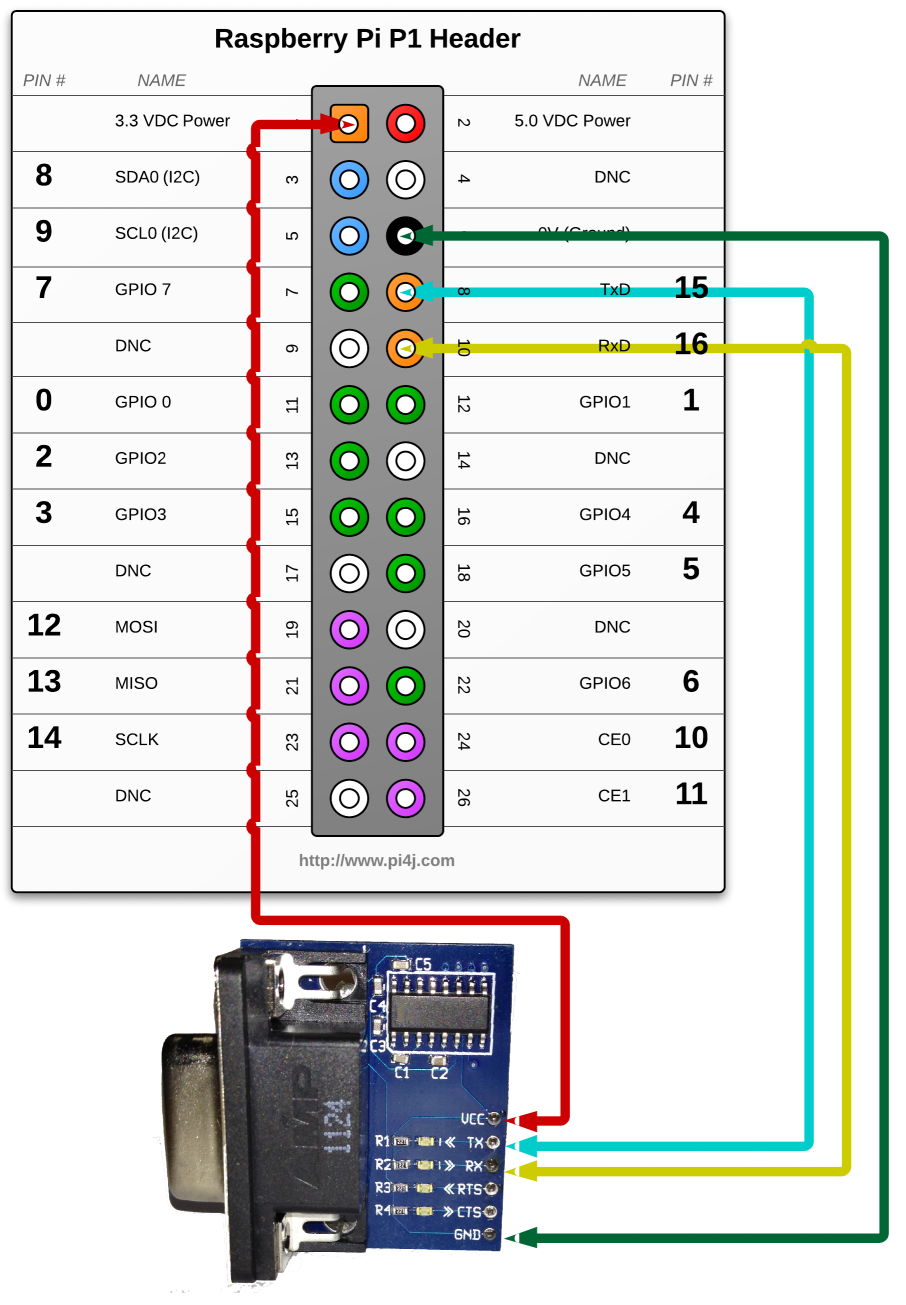
It does, and there is. However, I'm unsure what point you are trying to make with that remark.menno2000 wrote:Wouldnt this image ... Suggest there is also 5v available on the Raspberry Pi? (Pin 2).
So I'm using OTGW-USB model, and it works quite well!The pins use a 3V3 logic level and are not tolerant of 5V levels, such as you might find on a 5V powered Arduino.
...
GPIO voltage levels are 3.3 V and are not 5 V tolerant. There is no over-voltage protection on the board - the intention is that people interested in serious interfacing will use an external board with buffers, level conversion and analog I/O rather than soldering directly onto the main board.