Page 1 of 1
Install Fgs 212 dimmer
Posted: Sat Aug 15, 2015 3:16 pm
by geritz81
Hi,
I am trying to install the new fibaro FGS 212 dimmer in between a lamp.
I am struggling with the fibaro drawing in combination with my setup.
Pretty basic set up, momentary switch which has 2 wires...1 Powered, 1 switch wire.
Tried a lot of combinations but best setup is switching the light on but immediately off (tried to play with the parameter 14 but no succes)
Can somebody explain me where to put which wire in switch and dimmer module ( N-L-IN-Q-S2-S1) ?
Appreciate the help (also went through different topic but no succes on my Side

)
Re: Install Fgs 212 dimmer
Posted: Sat Aug 15, 2015 7:01 pm
by Sooty
I assume you are referring to the FGD-212 dimmer?
The connections will depend if the dimmer is installed in 2-wire or 3-wire mode.
I have 3 of the FGD-212 dimmers installed in 2-wire mode with momentary switches.
Assuming the electrical connections are correct, then parameter 20 should be set to 0 for momentary switch type.
Paul..
Re: Install Fgs 212 dimmer
Posted: Sat Aug 15, 2015 9:52 pm
by geritz81
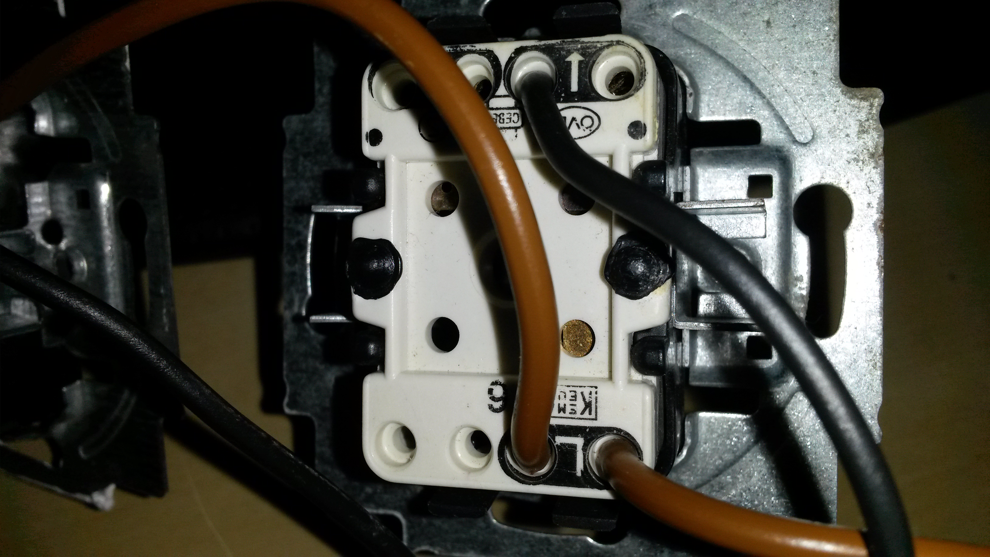
Indeed it is FGD-212, to be honest I am not very sure about the connections into the dimmer and to the switch.
I have a 2 wire setup, one brown (live wire) and black.
I tried to figure out the connections via the manual, but not sure I got it right

Anybody who has a picture of a 2 wire setup in a momentary switch ?
Re: Install Fgs 212 dimmer
Posted: Sun Aug 16, 2015 7:30 am
by Sooty
The attached image is based on standard UK wiring where Brown = Live, Blue = Neutral and Green/Yellow = Earth (Green in picture).
If standard 2-core + earth cable is used to the switch location then it is common practice here that the blue core is sleeved in brown to signify that it is being used as switched live and not neutral.
Paul..
Re: Install Fgs 212 dimmer
Posted: Sun Aug 16, 2015 10:55 am
by raymonvdm
I don`t think a uk schema will do much good if you live outside the UK
 http://www.fibaro.com/manuals/en/FGD-21 ... T-v1.0.pdf
On page 9 you need the first schema on the left (Wiring diagram no. 1 - 2-wire connection) for NL
L = connected to brown
S1 = connected to black of the switch (arrow on switch)
Sx = connected to the P / L of the switch (or the red corner depending on the type of switch)
N = connected to the P / L of the switch (or the red corner depending on the type of switch)
WaveArrow = Connected to the black wire going to the lampbulb
Switch back
Re: Install Fgs 212 dimmer
Posted: Tue Aug 25, 2015 10:48 pm
by geritz81
Worked perfect! thanks