Page 1 of 1
How connect LED's and RESET
Posted: Wed Feb 12, 2014 10:23 am
by Chriskras
I have some questions:
- How should the indicators (LEDs) are connected to the LED pin? What resistor do I need and where VCC (ground) I can connect him best.
- How the RESET must be connected?
- What the GPIO can be used?
Of course, all just looked on the site and forum but did not come out. Hence this question.
Re: How connect LED's and RESET
Posted: Wed Feb 12, 2014 6:39 pm
by hvxl
How to connect the LEDs is described in
this topic.
For a reset button you just need to connect a momentary switch (i.e. a switch that is only ON as long as you press it) between the two pins marked "RST".
Re: How connect LED's and RESET
Posted: Wed Feb 12, 2014 9:52 pm
by vasco_nl
And what about the gpio. I cannot find any usefull information about that on the website.
Re: How connect LED's and RESET
Posted: Wed Feb 12, 2014 10:14 pm
by Chriskras
Gpio pin is only for outside temperate sensor? Wich type can i connect?
For leds, I've already read it. Now all I have how do I connecten him? Connect one side of the LED? And the other with a resistor to ground? What resistor should I use? How do I connect the LED? Is there a diagram of how this will work in them? Reset pin can I do with a jumper? Jumper connect a reset?
Re: How connect LED's and RESET
Posted: Wed Feb 12, 2014 10:25 pm
by hvxl
vasco_nl wrote:And what about the gpio. I cannot find any usefull information about that on the website.
I'm sorry that you don't find the provided information useful.
Re: How connect LED's and RESET
Posted: Wed Feb 12, 2014 10:49 pm
by hvxl
Chriskras wrote:Gpio pin is only for outside temperate sensor? Wich type can i connect?
For leds, I've already read it. Now all I have how do I connecten him? Connect one side of the LED? And the other with a resistor to ground? What resistor should I use? How do I connect the LED? Is there a diagram of how this will work in them? Reset pin can I do with a jumper? Jumper connect a reset?
The GPIO pins are not only for outside temperature sensor. As mentioned on the website, with firmware 4.0b3 there are several functions to choose from:
- Ground - A permanently low output (0V). Could be used for a power LED.
- Vcc - A permanently high output (5V). Can be used as a short-proof power supply for some external circuitry used by the other GPIO port.
- LED E - An additional LED if you want to present more than 4 LED functions.
- LED F - An additional LED if you want to present more than 5 LED functions.
- Setback, low active - Set thermostat to setback temperature when pulled low.
- Setback, high active - Set thermostat to setback temperature when pulled high.
- DS1820 (GPIO port B only) - Data line for a DS18S20 or DS18B20 temperature sensor used to measure the outside temperature. A 4k7 resistor should be connected between GPIO port B and Vcc.
As mentioned in that list, you can connect a DS18S20 or DS18B20.
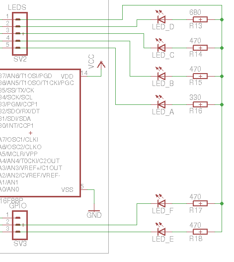
You connect the cathode of the LED to one of the LED pins of the gateway and the anode via a resistor to Vcc (not to ground). Vcc is available at the pin marked 1 on the header. You may also put the LED and the resistor in reverse order.
As mentioned on the site, use a resistor between 180 Ohm and 1 kOhm. Pick whatever value gives you the desired brightness for the type of LED you use. In the topic I referred you to earlier I have indicated the values I use.
I suggest you connect the LEDs with half of
Conrad orderno 743135-89.
If you briefly put a jumper on the reset pins, that will indeed reset the gateway.
Re: How connect LED's and RESET
Posted: Fri Feb 14, 2014 11:16 am
by Chriskras
I just made a schematic. Is it true if I connect them?

Bigger pic:
http://oi60.tinypic.com/jagufo.jpg
Re: How connect LED's and RESET
Posted: Fri Feb 14, 2014 6:53 pm
by hvxl
No, that's not correct. You need to connect the LEDs the other way around. And the resistors for all LEDs must be connected to Vcc, including those for LEDs 5 and 6. With 180 Ohm resistors the LEDs will be very bright.
Re: How connect LED's and RESET
Posted: Fri Feb 14, 2014 8:15 pm
by Chriskras
What do you mean? Can you make a schematic for my?
It's just easier to understand for me
Re: How connect LED's and RESET
Posted: Tue Feb 18, 2014 10:54 pm
by hvxl
So nobody is able to make a picture based on the provided description and it's down to me again?
It really isn't that complicated:
Re: How connect LED's and RESET
Posted: Wed Mar 05, 2014 8:42 pm
by gizmocuz
hvxl wrote:So nobody is able to make a picture based on the provided description and it's down to me again?
It really isn't that complicated
Not for a genius like you!